Design Brief
“Design and manufacture a machine that can lift a weight of 10 pounds over a vertical distance of 1 inch within minute, with a maximum boom deflection of half an inch.”
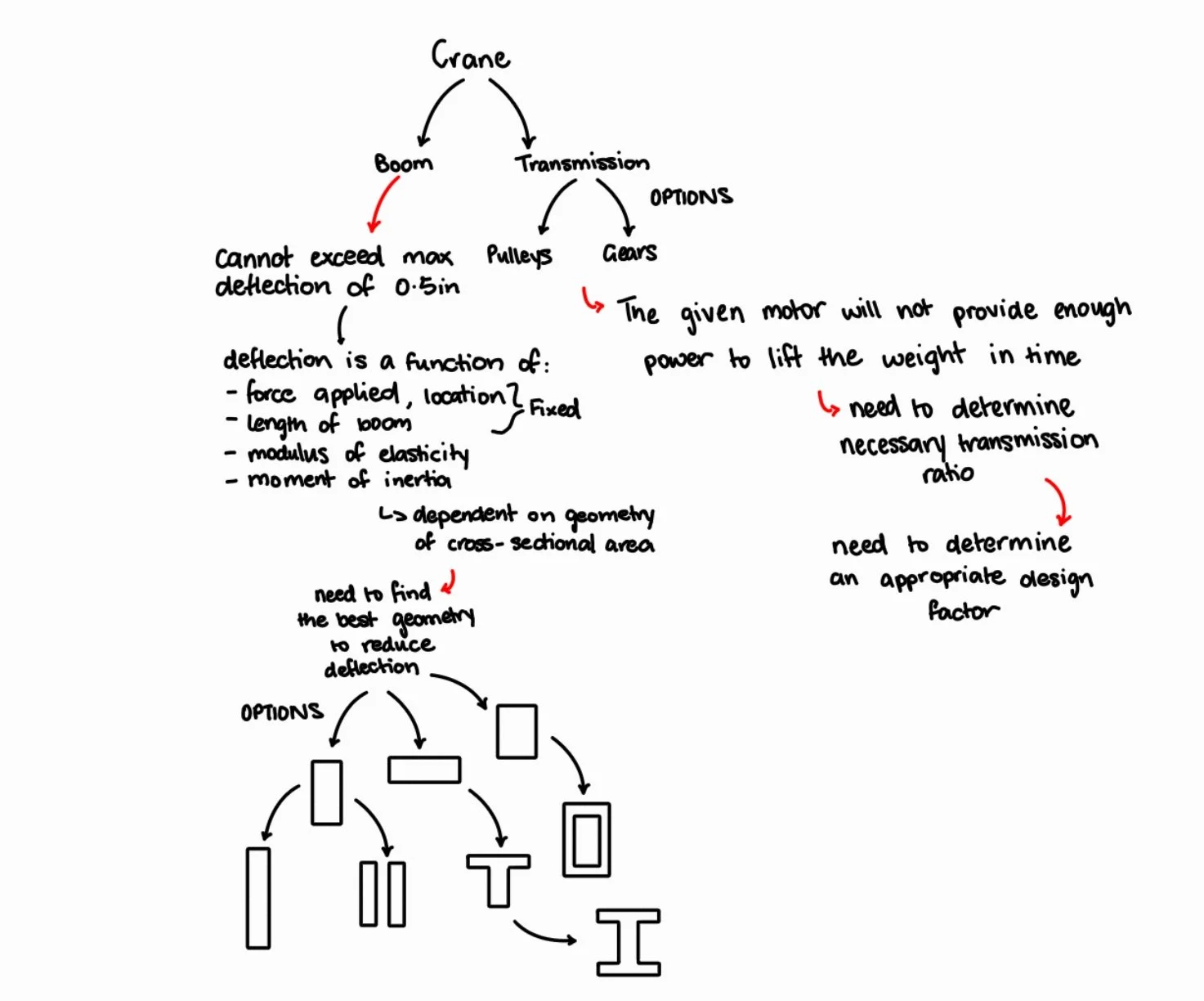
To begin the iterative design process, the problem was broken down into two primary component systems:
CAD Drawings
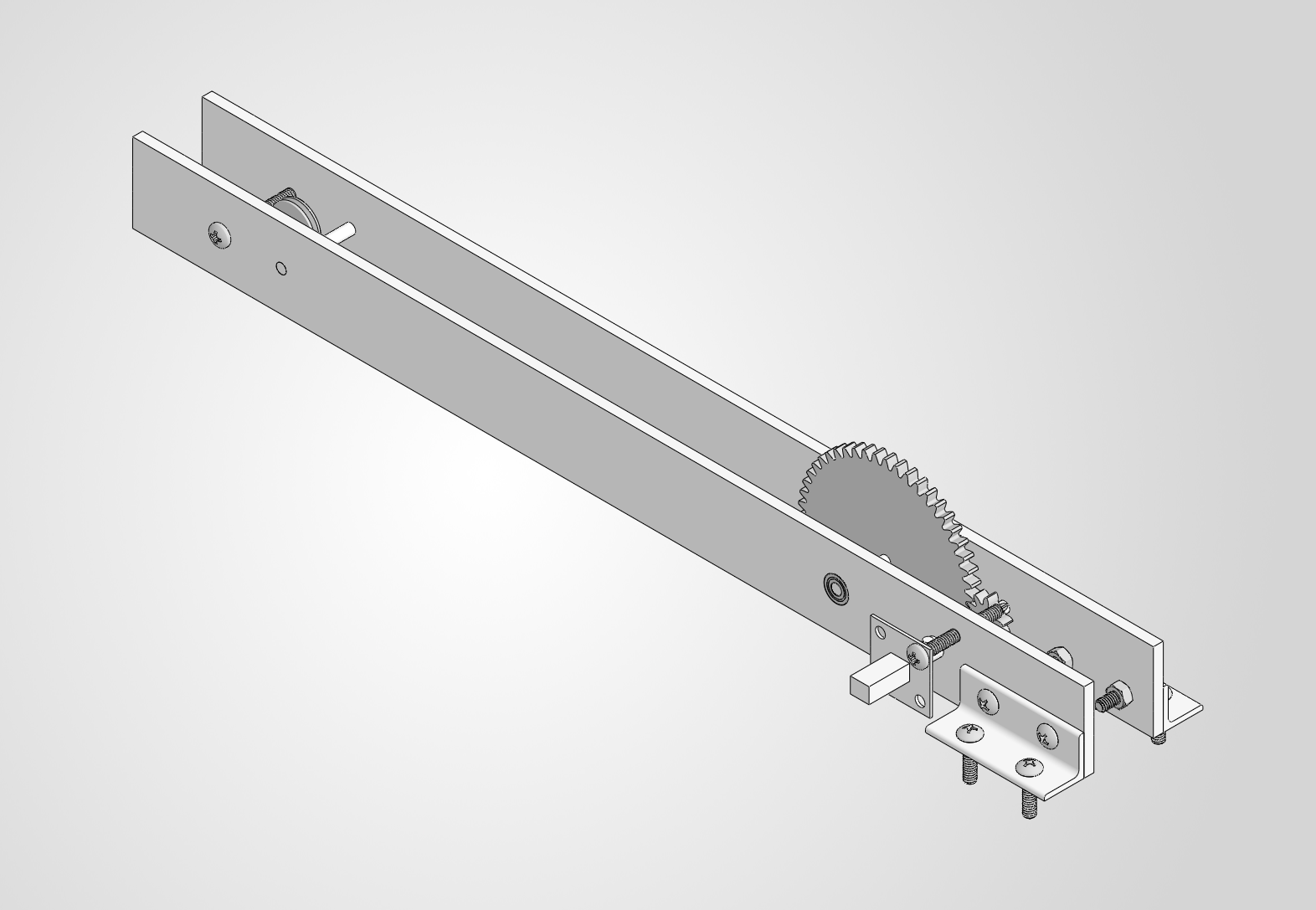
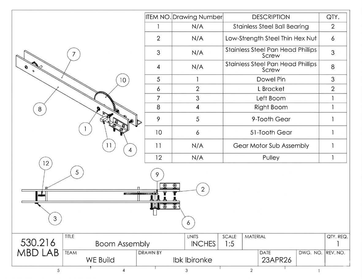
The final design includes the split boom, gear train, L-brackets to fix the boom to the table, and dowel pins that would support the string the 10-pound weight hangs from. The CAD drawings of this design that were used to produce each of these components is shown below:
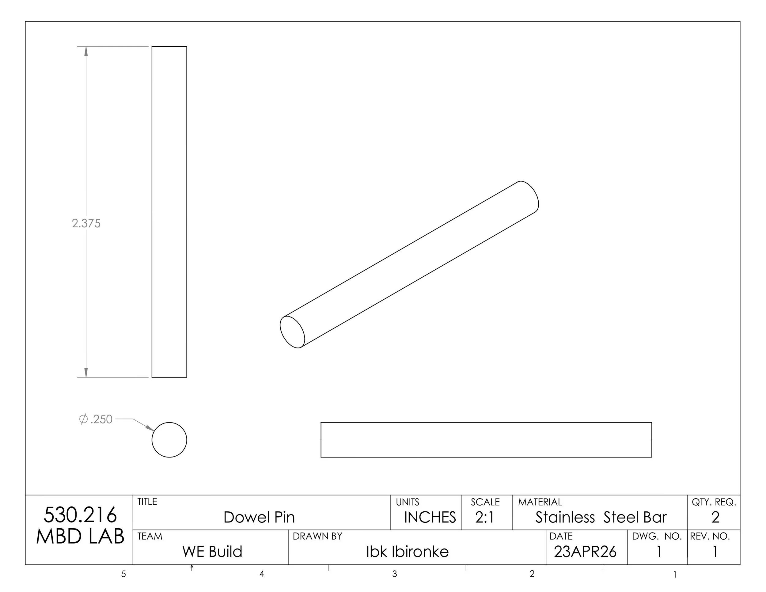
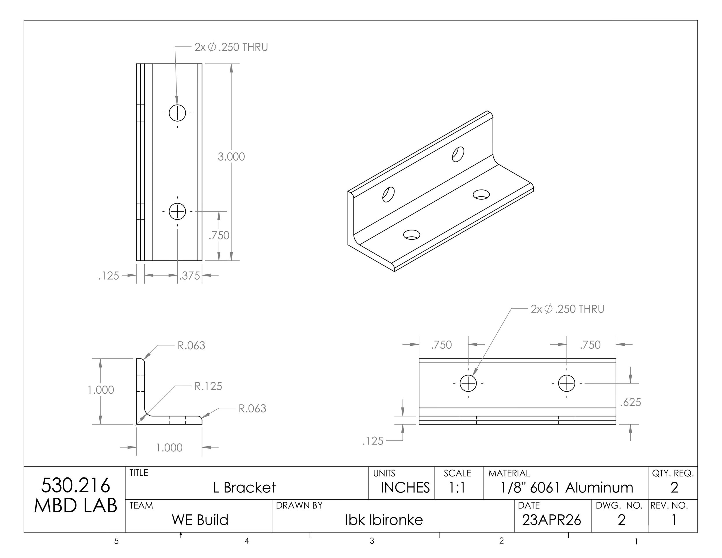
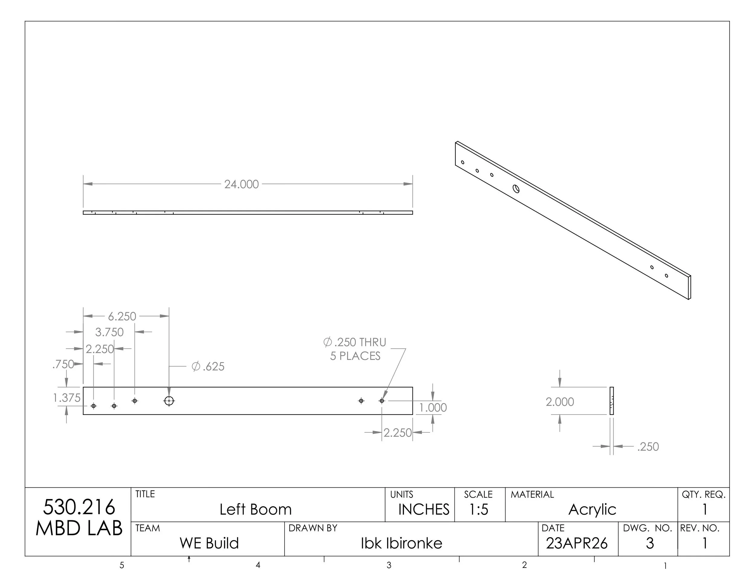
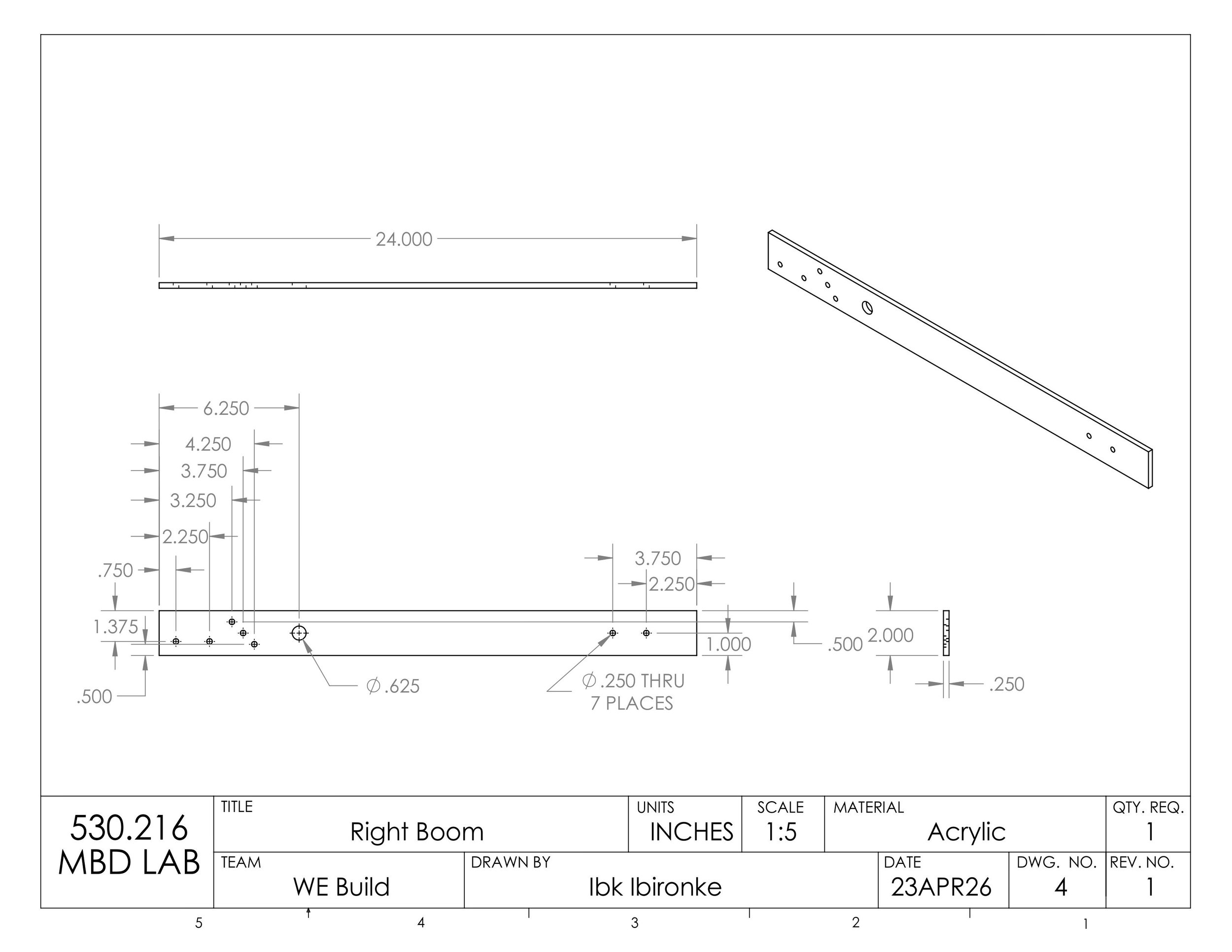
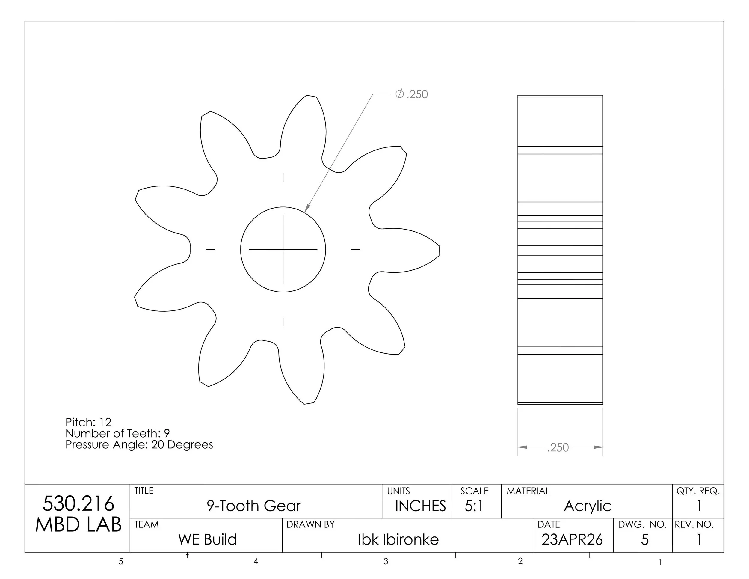
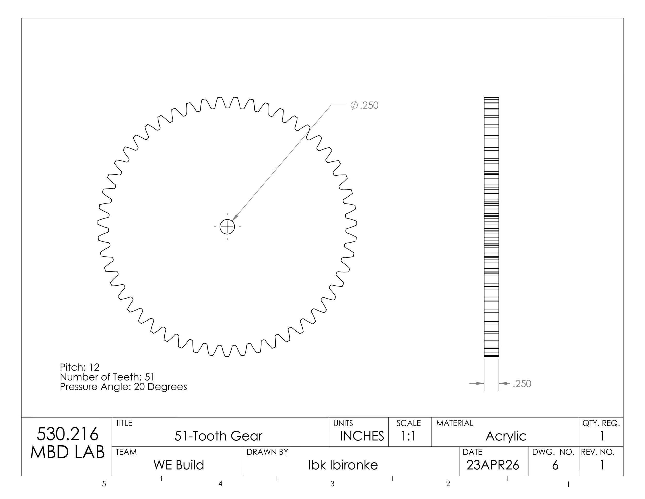
Final Design Description
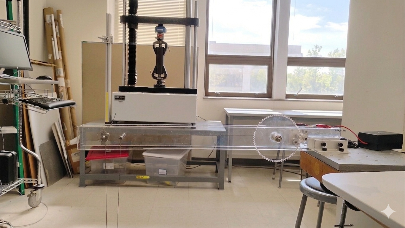
The lifting machine (pictured to the left) consists of a horizontal boom constructed from acrylic, with an overall length of 24 inches. The boom has a rectangular cross-section and is mounted to the base plate using L-brackets and fasteners, providing a rigid connection while allowing load transfer to the mounting plate.
The power transmission system uses a gear train consisting of a 12-tooth gear and a 68-tooth gear, driven by a DC gearmotor. This setup provides a gear ratio that increases torque at the output shaft.
Important Calculations
All calculations that were carried out to inform design decisions can be found here:
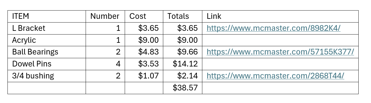
Total Cost
Total amount spent on additional materials:
Performance Evaluation Summary
Overall, the lifting machine successfully met all the criteria given in the brief for this project. It raised the 10-pound weight by 1 inch in under half the required time, with a boom deflection of 0.3 inches and 13% under budget.